8.2 GENERAL DESIGN CONSIDERATIONS FOR PROPELLANT TANKS
The tank design is greatly influenced by systems optimization within the overall vehicle design. A principal design objective is for the vehicle to yield the highest payload and/or velocity increment with maximum possible reliability. Design details depend largely upon type of propellants, vehicle mission requirement and configuration, propulsion system design, and available construction materials and fabrication techniques. Some of the most important considerations follow.
Propellant Properties
Propellants affect tank design mainly by their physical and chemical characteristics. The boiling point or storage temperature of a propellant determines the operating temperature range of the tank assembly. Cryogenic propellants cause tank design problems from thermal gradients, from the need for insulation and from the need for construction materials capable of remaining ductile at very low temperatures. The very low density of some propellants, such as liquid hydrogen, requires tanks of considerable volume. The highly corrosive and reactive properties of other propellants severely limit the selection of tank materials.
Shape and Size of Propellant Tanks
Propellant tanks are pressure vessels. Disregarding other factors, the lightest pressure vessel for a given volume is a spherical shell, since it has the smallest surface to volume ratio. It also has the smallest shell stress for a given internal pressure. While a sphere may be the lightest pressure vessel, the combination of several spheres into the generally cylindrical envelope typical for most rocket vehicles would cause a sizable volume penalty. Furthermore, a sphere would preclude the use of the tank wall as a load-carrying member of the vehicle structure (figs. 8-1 and 8-2), resulting in further weight and volume penalties.
Thus both vehicle configuration and tank pressure level will determine the shape of propellant tanks. For vehicles of relatively large length-to-diameter ratios and of limited space envelopes, cylindrically shaped tanks are used. For relatively high tank pressures and less stringent space conditions, spherical tanks may be employed to best advantage (fig. 8-3). The ends of cylindrical tanks can have either spherical or ellipsoidal shapes. The basic cylindrical tank with spherical ends is lighter than one with ellipsoidal ends. However, the overall weight of an ellipsoidally ended tank may be less when the shorter interstage structure required is considered. In some designs the propellant tank aft ends are faired into conical or other special shapes to accommodate the thrust loads from engine assemblies as well as to minimize trapped propellants.
The required size or volume of a propellant tank is the sum of usable propellant volume and other volume requirements:
where
$V_{t}=$ propellant tank design volume, $\mathrm{ft}^{3}$
$V=$ usable propellant volume calculated from
    propulsion system requirements, $\mathrm{ft}^{3}$ (may
    include a "usable residual" term repre-
    senting design reserves, mixture ratio
    shift effects, etc.)
$T=$ trapped propellant volume. This is a func-
    tion of system design configuration and
    includes propellants trapped in tank,
    ducts, thrust chamber cooling jacket,
    etc., $\mathrm{ft}^{3}$
$B=$ boiled-off propellant volume (applicable
    only to cryogenic propellants), $\mathrm{ft}^{3}$
$U=$ tank ullage volume, $\mathrm{ft}^{3}$
The calculation of propellant volume is based on the propellant density at specific temperatures. A standard temperature of is used for storable propellants. Boiling point conditions at ambient pressure are used for the cryogenic propellants. The tank ullage-volume calculations should allow for propellant volume changes due to temperature change of the tanked propellant, and for tank deformation when pressurized. This is especially important for prepackaged storable liquid systems to prevent excessive tank ullage pressures when the system is exposed to a specified upper temperature limit during storage. Adequate ullage volume is also required to maintain tank pressure at starting when the relative ullage volume increase is large and may tax the response of the pressurization system.
Sample Calculation (8-1)
The following data are given for the A-4 stage propulsion system, including two engines:
Oxidizer density, Oxidizer weight flow rates, engine Fuel density, Fuel weight flow rate, engine Nominal engine firing duration at full thrust, 410 sec Trapped oxidizer volume, Trapped fuel volume, Tank ullage volume, of propellant volume Determine the volume of the propellant tanks.
Solution
The required usable oxidizer volume
The oxidizer tank ullage volume
From equation (8-1), the required design volume of the oxidizer
The required usable fuel volume
The fuel tank ullage volume
From equation (8-1), the required design volume of the fuel tank
Propellant Tank Arrangement
In most vehicle systems, the propellant tanks are arranged in tandem. Other arrangements are used for specific design reasons. Figure 8-4
 AND SEPARATE HEUUM BOTTLES -
TANKAGE WEIGHT. 100 PERCENT
AND SEPARATE HEUUM BOTTLES -
TANKAGE WEIGHT. 100 PERCENT
 (b) TANDEM PROPELLANT TANKS WITH INTEGRATED HELIUM BOTTLE IN THE MIODLE TANKAGE WEIGHT, 93 PERCENT
 (c) CONCENTRIC PROPELLANT TANKS WITH INTEGRATED HELIUM BOTTLE AT AFT ENO tankage weight, its percent
 (d) MULTIPLE PROPELLANT TANKS AND HELIUM BOTTLE IN CLUSTER - TANKAGE WEIGHT, 162 PERCENT
Figure 8-4.-Various propellant tank arrangements of a typical vehicle system. presents various propellant tank configurations for a typical vehicle system using helium for tank pressurization. A design analysis will determine the best solution for a given propellant storage volume and vehicle space envelope. General considerations are: (1) Minimum overall weight (2) Maximum storage volume in a given envelope (3) Least possibility of propellant mixing (4) Clean aerodynamic vehicle shape (5) Ease of installation of ducts and lines (6) Ease of insulation (7) Ease of fabrication and handling (8) Minimum trapped (unusable) propellants
Arrangement (a) is taken as standard. Arrangement (b), combining tandem propellant tanks with an integrated helium bottle in between, results in lowest weight; however, it poses design problems in the routing of pneumatic lines and controls. Arrangement (c) with concentric tanks eases the installation of propellant ducts, but has the possibility of simultaneous puncture of both tanks (by bullets or from other causes), and subsequent mixing of the propellants. Arrangement (d) with multiple tanks has the highest weight, but is easier to fabricate and handle especially for very large vehicles.
Working Loads
The propellant tanks are structural members which must be designed to withstand a combination of the following probable working loads: (1) Internal pressure loads and their dynamic effects (2) Axial thrust loads and their dynamic effects (3) Bending moments due to vehicle transverse accelerations, wind loads, and shifting of the center of gravity (4) Aerodynamic forces (5) Thrust vector control forces (6) Vibration loads (7) Loads produced by mounting arrangement (8) Loads caused by thermal transients and gradients (9) Loads produced during ground handling
In most vehicle systems, internal tank pressure loads and axial thrust loads are the principal ones. Other loads require careful evaluation, including model tests or full-size experiments.
Safety Factors for Propellant Tank Designs
The recommended criteria for working loads presented in chapter II (eqs. 2-8 through 2-11) are generally applicable to propellant tank designs. However, when calculating allowable working stresses from tank internal pressure, the following correlations are recommended for various situations: (1) No hazard to personnel or vital equipment:
or
(2) Special safety devices are provided for personnel (example: the booster for a manned upper stage which has an ejection device with an exceptionally high degree of reliability):
or
(3) Hazard to personnel or vital equipment:
or
where maximum allowable working stress, psi; i.e., the stress due to maximum tank working pressure under normal transient and steady operating conditions yield strength, psi, of the tank construction material, at operating temperature conditions ultimate strength, psi , of the tank construction material under operating temperature conditions is calculated for both and . The lower value should then be used. All propellant tanks are subjected to hydrostatic pressure tests prior to acceptance. For case (1), the proof test pressure equals maximum tank working pressure.
For case (2) and (3), the proof test pressures should be 110 percent of the maximum tank working pressure. For high-pressure inert gas, longduration storage bottles, the following correlations are recommended:
No hazard to personnel:
Hazard to personnel:
Sample Calculation (8-2)
The start transient of a prepackaged storable liquid propulsion system for an aircraft-launched missile is programed not to reach main-stage level until the missile is at a specific distance from the aircraft.
Calculate the maximum allowable working stresses for the propellant tanks, if they are made of- (a) Aluminum alloy 6061-T6, ,
(b) Aluminum alloy 6066-T6, ,
Solution
(a) Tank made of aluminum alloy 6061-T6.Since the system involves personnel safety during start transient, equations (8-6) and (8-7) will be applied.
or
Thus, the maximum allowable working stress during start transient .
During mainstage operation, personnel are considered safe and equations (8-4) and (8-5) can be used:
or
The maximum allowable working stress for mainstage . (b) Tank made of aluminum alloy 6066-T6.During start transient
or
The maximum allowable working stress during start transient .
During mainstage operation
or
The maximum allowable working stress during mainstage .
Material and Fabrication Considerations in Propellant Tank Design
In addition to considerations of propellant compatibility and operational temperature ranges, selection of construction materials for propellant tanks is based on their strength-to-density ratio at a given temperature and on their ductility. For a given working pressure, the lightest tank structure will be the one made of the material with the highest ratio of ultimate strength to density. Most frequently used construction materials for propellant tanks are: (1) Aluminum alloys, such as 6061-T6, 6066-T6, and 2014-T6. Room temperature properties: Average density up to up to (2) Stainless steels, such as AISI 347 (for low-pressure tanks only), 17-7 PH and PH . Room temperature properties: Average density , up to 200000 psi . up to 220000 psi. (3) Fiber glass, filament wound with an aluminum-alloy liner. Room temperature properties (fiber glass only): Average density . Aluminum alloys are compatible with most storable and cryogenic propellants, and may be used for working temperatures up to . Stainless steels are suitable for storable (limited duration) and cryogenic propellants, and are suitable for higher temperatures ( maximum). Fiber glass is limited to moderate temperature conditions ( to ).
Fabrication methods for propellant tanks depend largely upon the type of material used. Most important considerations for tank fabrication are dimension control, heat treating, and welding. The lowest recommended wall-stock size for propellant tanks is about 0.010 inch for stainless steels and 0.020 for aluminum alloys. While tank stress calculations must consider the lower limit of wall-thickness variation, the upper limit is used for tank-weight calculation. The strength of a metal may fall into a band, too, the width of which depends on the heat-treating process. Stress calculation will be based on the minimum expected strength. The quality of the welding process or the efficiency of a welded joint may require extra stock added to the wall thickness as calculated from other working stresses. An assumed weld efficiency of 85 to 95 percent is a reasonable value for steels ( 50 to 65 percent for aluminum). To minimize weight penalties, build-up lands may be used at the welds (fig. 8-9) for an equivalent 100 percent weld efficiency. Figure presents the construction of a welded propellant tank. Note the segmented tank end which is typical for largesize tanks.
Other Propellant Tank Design Problems
Many other design and analysis problems will have to be carefully considered before a successful propellant tankage can be produced. The relatively thin, highly stressed shells make it difficult to attach concentrated loads. The loads must be spread out in a suitable way to prevent localized overstresses. Cryogenic propellants may create thermal transient and gradient problems. While the empty portion of a tank may be
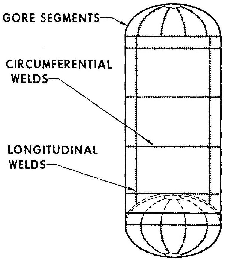 Figure 8-5.-Typical welded propellant tank construction.
subject to aerodynamic heating, the filled portion may be at a very low temperature. Additional thermal problems may arise in outer space, from solar heating of one tank side and radiation cooling of the other.
Also partly the tank designer's responsibility is the solution of certain problems associated with the management of the propellants within the tanks, such as: (1) Uniform dispersion of the entering tank pressurant (2) Sensing of propellant quantities (PU) (3) Prevention of propellant sloshing (4) Expulsion of the propellants under adverse conditions (5) Fill, drain, vent and pressure relief of the propellant tanks